Work, in the centre.
A 16-inch MacBook is the typing surface, with a Studio Display above it. Screen alignment and the adjustable stand are part of the layout study.
 Paul Béglin.Say hello
Furniture & product design · 2026
A place to work.
Designed to leave space.
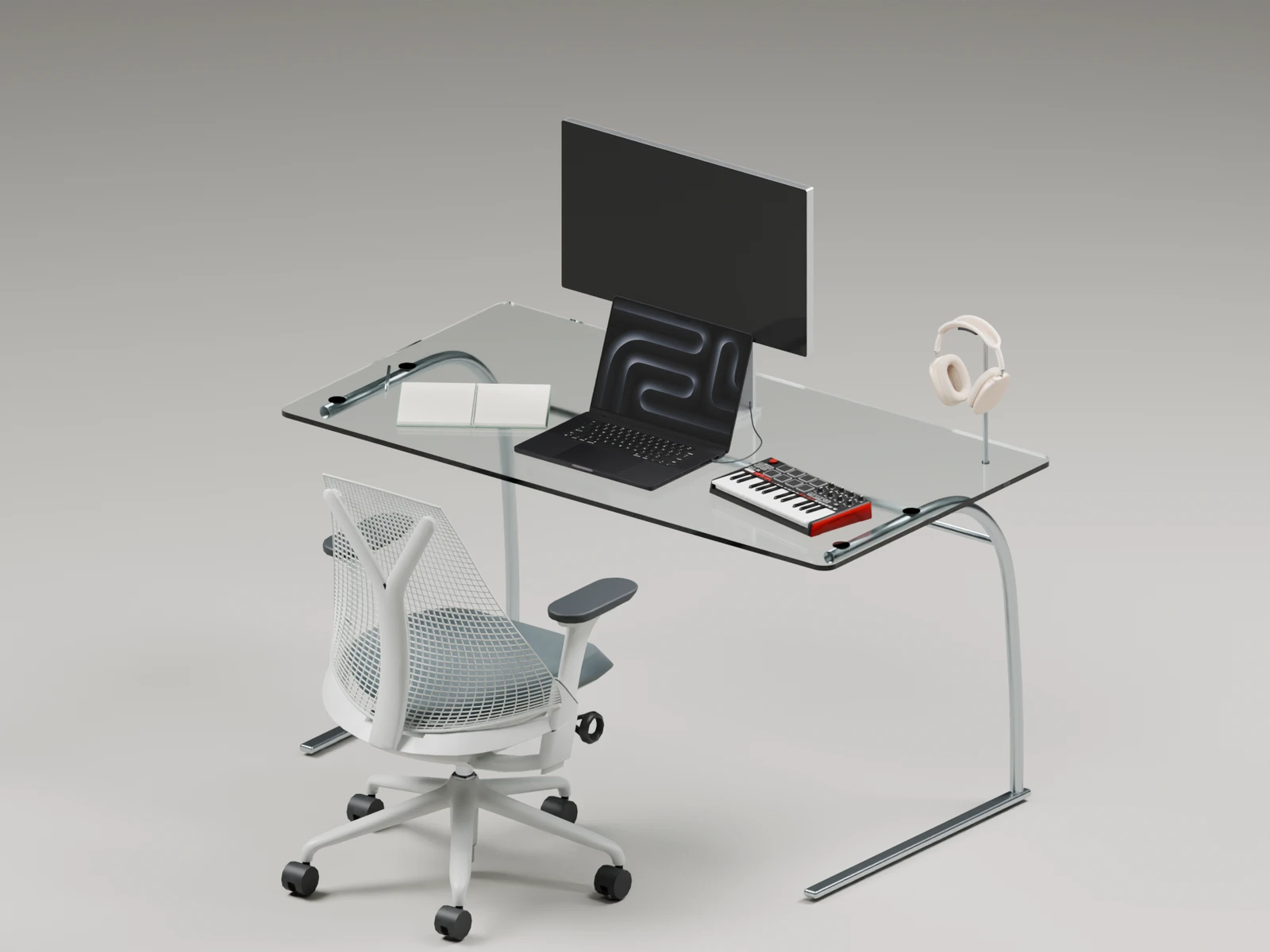
I wanted a clear glass surface, a clean computer setup, and room to move underneath without bumping into bulky desk legs.
The first sketch borrowed a thought from architecture: flying buttresses. A support could curve towards the surface, carrying its weight while leaving the space around it open.
That became a pair of cantilevers, one on either side. The challenge is making something that looks light feel steady in everyday use.
The objects make the idea concrete. Where do I write? How do the two screens line up? Is there room to play a few notes without rearranging everything?
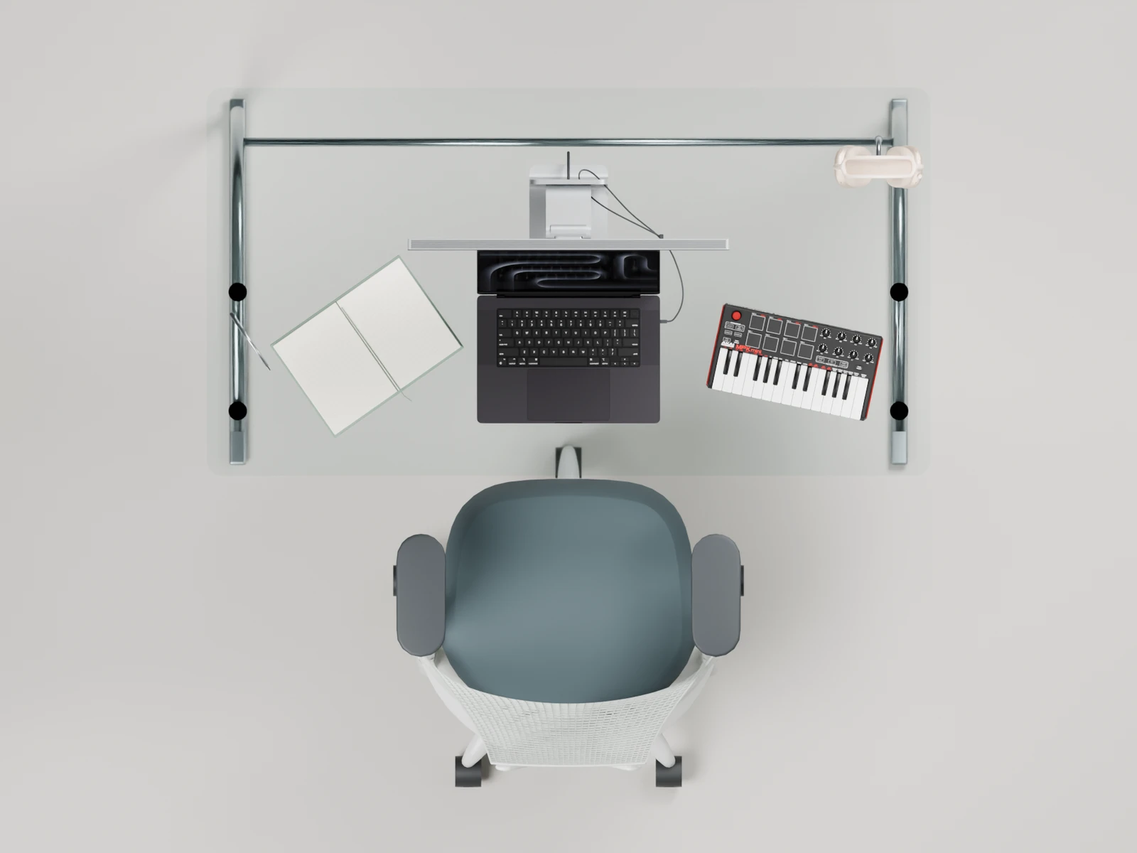
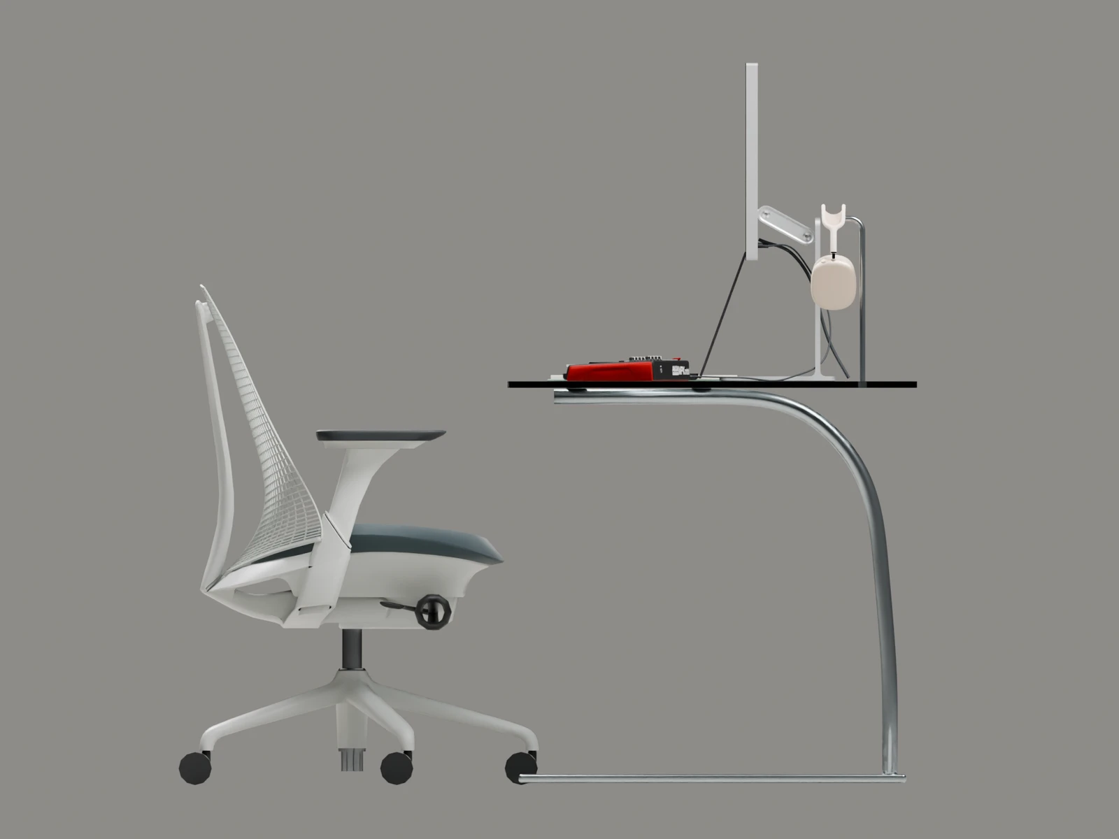
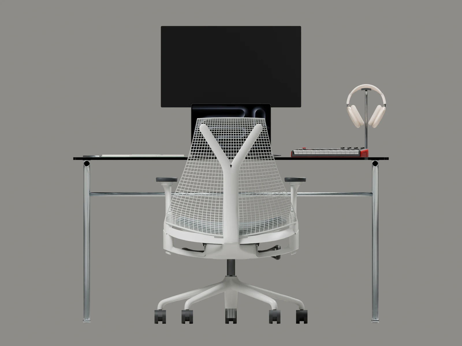
A 16-inch MacBook is the typing surface, with a Studio Display above it. Screen alignment and the adjustable stand are part of the layout study.
An angled A5 notebook and a pen sit on my writing side. I’m left-handed, so this space deserves as much attention as the screens.
An Akai MPK Mini and AirPods Max have their own place. A curved metal headphone holder continues the language of the desk supports.
A standing version explores how the glass surface and curved supports could move together on telescopic columns, rising from 740 to 1,160 mm.
The aim is to change posture without rearranging the workspace. The animation shows the movement concept; the lifting mechanism and its stability still need development.
A convincing render is only the beginning. The next questions are about bending, balance, connections, and how someone would actually make it.
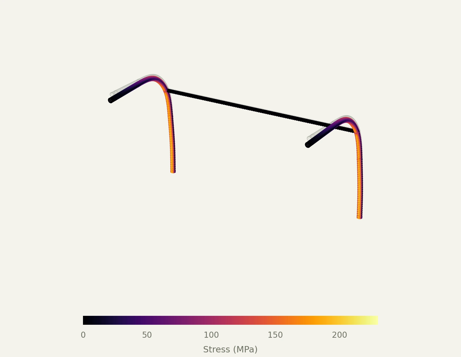
An additional 40 kgf (392 N) acts over a small patch at the front centre, on top of self-weight and the earlier equipment loads. These are saved FEM results, not physical measurements.
von Mises stress
Maximum principal tensile stress
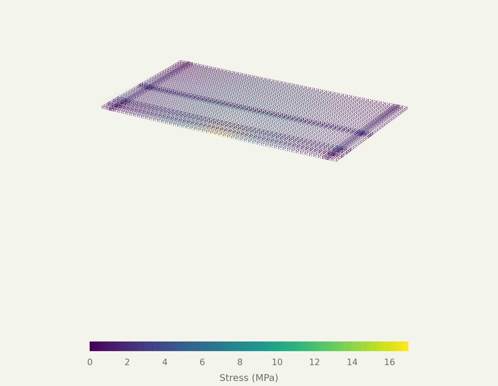
Ideal retained pads and fixed frame roots. Earlier equipment layout; the MPK Mini and revised fittings are not included. This is a preliminary linear-elastic study, with large-deflection limitations at this load.

Round steel tubes: 28 mm outer diameter, 2 mm wall. Hypothetical S235 steel, with a 235 MPa yield threshold. The glass is modelled elastically without a fracture criterion. The front load acts over a 150 × 60 mm patch rather than a single point.
The sweep uses linear superposition of saved solver cases. It assumes that the glass is positively retained: loose pads cannot hold the current top in static balance. Real adhesive bonds, welds, floor contact, tipping, tube buckling, impact and fatigue are not validated.
The fine mesh contains 90,498 nodes and 15,972 elements. A two-mesh comparison changed front-centre movement by up to 2.8% and peak steel stress by up to 6.4%. Neither these results nor the estimated first-yield threshold establish a safe working load or a service life.
The rendered frame uses round tubes. I’m also studying a 28 × 40 mm oval section: deeper in the direction of bending, while keeping a narrow profile from the front.
The glass and equipment are only part of the load. Leaning on the front edge creates a different, more demanding case. Preliminary simulations exposed too much flexibility in the original thin frame.
Retaining the glass, preventing sliding, and attaching the headphone holder need their own checks. Adhesive pads and the flush fitting are concepts, not validated connections.
Current concept dimensions. The design has no verified load rating or durability claim.